
by: Avîrvarei Andrei | Amariei Gheorghe, EMC Eng. | Viorel Zăbavă, MSc.EE
RF Engineering | ROWAVES®
Abstract
The primary goal of this document is to provide a comprehensive guide for ensuring the optimal performance, reliability and longevity of microwave coaxial cables and connectors. It aims to highlight best practices for routine maintenance, inspection and handling, to minimize signal degradation and prevent costly failures. Additionally, the document seeks to educate readers on identifying common issues, implementing preventive measures and adhering to industry standards for maintaining high-frequency transmission systems.
Connectors for coaxial cables
Coaxial connectors operate from DC to millimeter-wave frequencies and are available for RF/microwave applications up to 125GHz [1].
Depending on the application and the type of connector intended for use, costs can vary significantly, ranging from a few cents to tens of euros. For example, basic connectors may cost as little as $0.25 per pair, while specialized connectors can be priced between $2.00 and $3.00 per pair. The cost is also determined by the quality of the connector. It is crucial to fully understand the application in which the connector will be used to ensure the right choice.
Advancements in connector technology have enabled operations beyond 100GHz. For instance, Anritsu’s VectorStar VNA system utilizes 1.0 mm coaxial connectors to cover frequencies from 70kHz to 125GHz in a single sweep [8]. Using a low-frequency connector in a microwave application can lead to performance issues, while using a microwave connector in low-frequency applications can result in unnecessary wear and inefficiency [1].
Fig. 1 is presenting examples of various types of connectors and their corresponding operating frequency ranges (see Annex 1 for details).
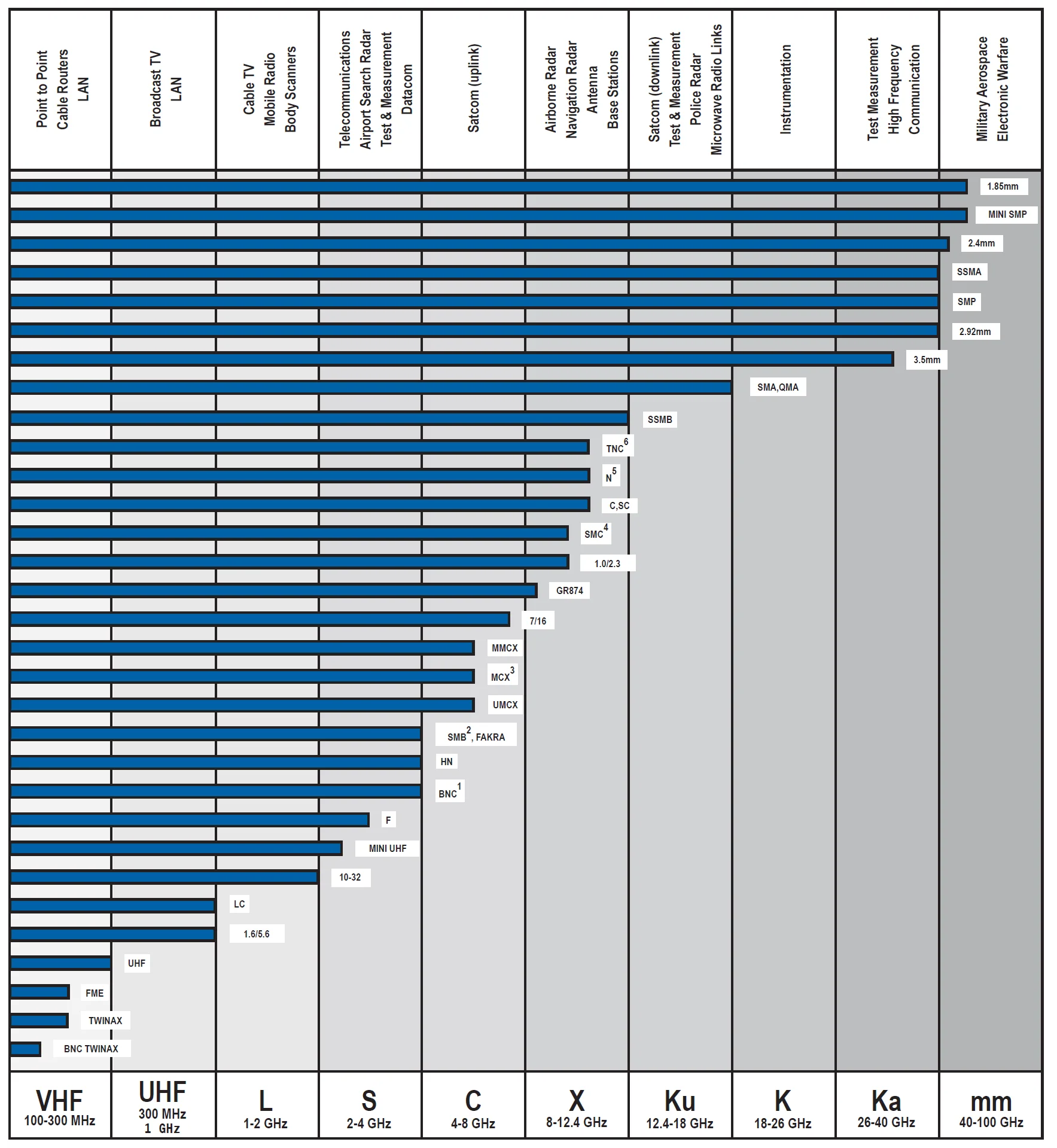
Figure 1. Coaxial connectors and operating frequencies [see full size picture in Annex 1]
Characteristic impedance
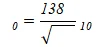
The characteristic impedance of coaxial cable is a function of its mechanical dimensions and a uniform dielectric constant [2]. Fig. 2 shows a coaxial connector structure.
- D is the inside diameter of the outside conductor or shield
- d is the outside diameter of the inner conductor
- is the relative dielectric constant of permittivity
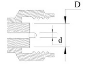
Figure 2. Characteristic impedance of a RF connector [2]
Two important requirements of coaxial transmission lines are: minimum insertion loss and good power handling [1].
In an air-filled coaxial transmission line, minimizing signal loss per unit length favors a D/d ratio of approximately 3.6, yielding a characteristic impedance of 77Ω. Conversely, maximizing power handling requires a different geometry, with an optimal D/d ratio around 1.65 and a characteristic impedance of 30Ω in free air [1].
When discussing characteristic impedance, we often consider 50Ω vs. 75Ω. Comparing 50Ω and 75Ω coaxial cables, the key differences lie in power and signal transmission. 50Ω cables offer better performance for high-power applications, such as cellular boosters, broadcast transmitters and Wi-Fi, as they handle higher power levels and minimize signal loss over long distances. These cables are commonly used in commercial systems and require larger connectors. In contrast, 75Ω cables are ideal for lower power applications like home entertainment systems, supporting devices like TVs and Blu-Ray players, where efficiency in signal transfer is more important than power. Homeowners typically opt for 75Ω systems due to their compatibility with smaller installations, while 50Ω systems are suited for larger areas or commercial/industrial use. The choice between the two depends on the specific needs of the system, such as range, power requirements and installation size.
A 50Ω characteristic impedance is commonly adopted in most RF and microwave applications as it represents a practical balance between minimizing signal loss and maximizing power handling capabilities [1][2].
Storage
Connectors should be stored in their original case (if existing), in a dry and clean environment and at the same temperature as the device where they will be used. They should not be placed on their contact surfaces or piled together with other connectors. Protective caps must be kept and reattached whenever the connector is not in use to prevent dust from contaminating the contact surfaces. Avoid touching the contact surfaces with your hands to prevent contamination [4][5].
In Fig. 3 is an example of how NOT to store connectors.
Storing connectors together with other components, such as screws contaminated with oil or dust, is a major mistake that can lead to connector damage [5].
When it comes to coaxial cables, they should be stored in a way that keeps them as straight as possible […] The bending radius should not exceed the maximum angle specified in the cable’s datasheet [4][5].
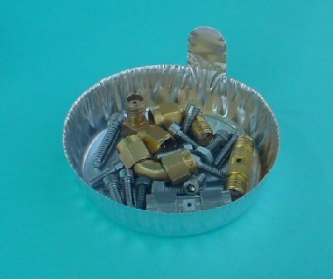
Figure 3. Incorrect way of storing connectors [5]
Maintenance
As shown in Fig. 4, we have an example of a connector contaminated with metallic fibers. A dirty connector with dust or metallic fibers may not cause issues at low frequencies, but at higher frequencies, it will hinder impedance matching. Moreover, during use, the abrasive nature of metallic fibers can create even more problems by damaging the mating surfaces of both connectors.
If we encounter such a connector, it is crucial to clean it thoroughly before any use [2][1].
Due to repeated connections and disconnections, connectors can degrade over time, even if they are well-maintained. Therefore, before each connection, the connector should be visually inspected in three steps:
- dirt inspection – We must be careful about dust particles and metal fibers on both the dielectric and the connector threads, as they can impact electrical performance [1].
- outer conductor – Inspect the outer conductor for deep scratches, displaced metal, dents, or uneven wear. Normal wear on the surface appears evenly distributed and without indentations.
- inner conductor – The male pin must be straight and centered to ensure proper coupling with the female pin. The contacts in the female connector are very precise and must be handled with care [2].
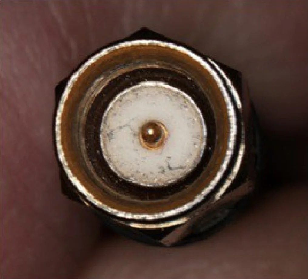
Figure 4. Contaminated SMA connector [2]
If, following the optical inspection, the connector needs cleaning, some very important tools are needed:
- low pressure, solvent-free compressed air
- isopropanol
- foam cleaning swabs
- lint-free cleaning cloth
- wooden cocktail sticks
With magnification and proper electrostatic discharge (ESD) precautions, the cleaning process should be carried out as follows [1][2][3]:
- blow out any loose debris using compressed air or nitrogen. Avoid blowing directly into the connector, as this could cause the debris to become more firmly lodged. Instead, blow across the connector’s face as shown in Fig. 5.
- inspect the connector with a magnifying glass. If debris is still present, attempt to remove it with a lint-free, foam-tipped swab (not cotton). Cotton swabs can leave behind fibers that are difficult to detect. Use the swab to gently wipe the surfaces. Applying excessive pressure may push debris deeper into the connector. Do not perform this step on connectors with air dielectrics.
Note: When using a swab, always clean the connector in a circular motion around the center pin, not across the pin, see Fig. 6 [2]. - use a swab moistened with isopropanol to clean the connector threads, moving in a circular motion around the connector, parallel to the threading [1][3] like in Fig. 7.
- re-inspect the connector – if further cleaning is needed, try using a foam swab with 99.5% isopropyl alcohol in a well-ventilated area. Apply only a small amount of alcohol to the swab, not directly to the connector. Gently wipe the surface with the swab. Do not perform this step on connectors with air dielectrics [1][2].
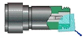
Figure 5. Correct direction of connector spraying [3]
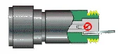
Figure 6.Correct method of cleaning / swab usage [3]
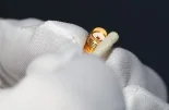
Figure 7. Detailed view for step 3 cleaning [1]
Handling coaxia connectors
The most important aspect when connecting a cable to a device is ensuring that the connector is compatible with the device’s connector. The key takeaway is to never attempt connecting two cables with different connectors if they are incompatible, as this will almost certainly result in permanent damage.
Before each connection, it is important to ensure that the two connectors are compatible; although they may look similar, this does not necessarily mean they are compatible, as improper connection can lead to damage to the connectors as shown in Fig. 5 [1][2][3].
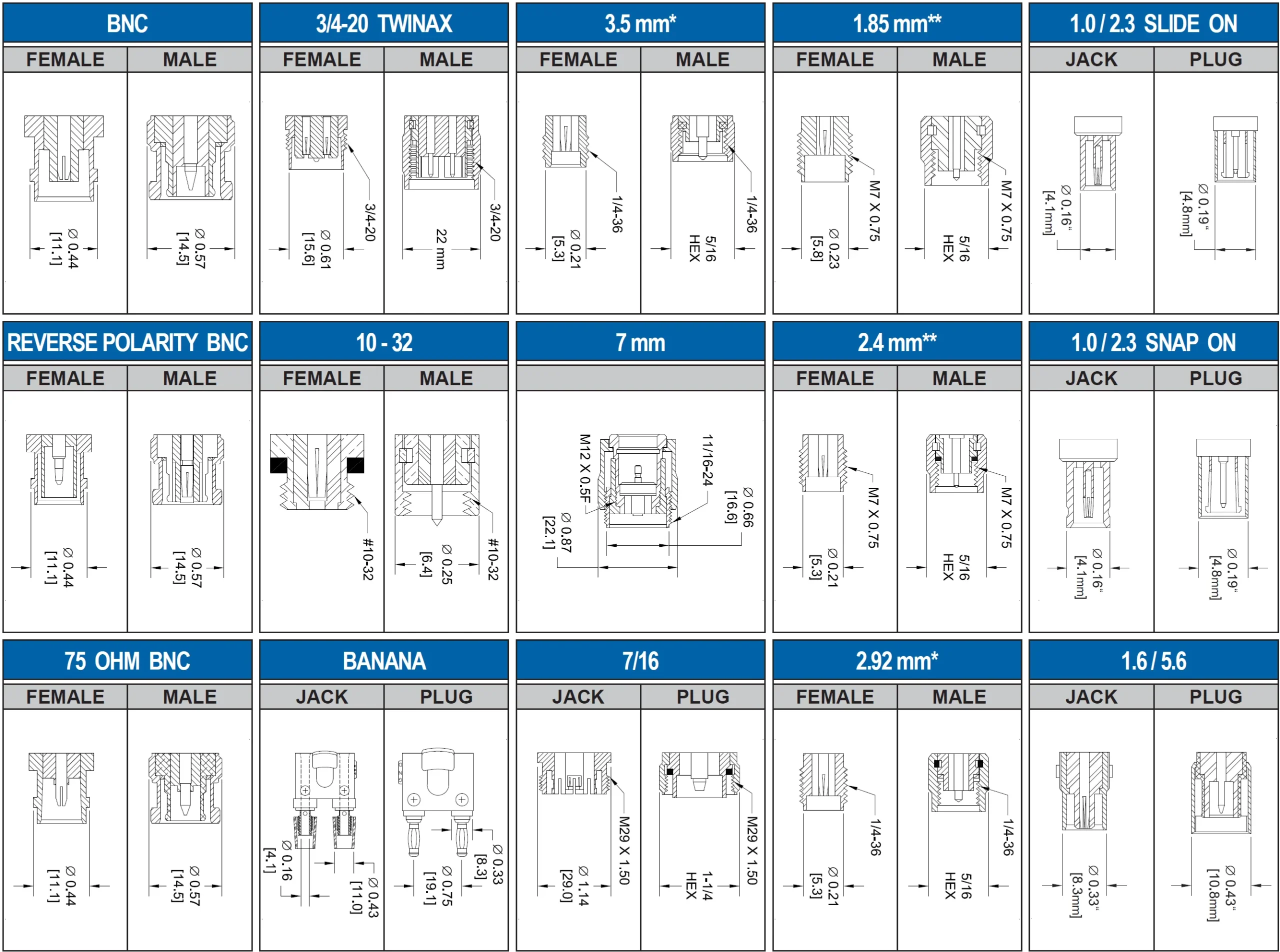
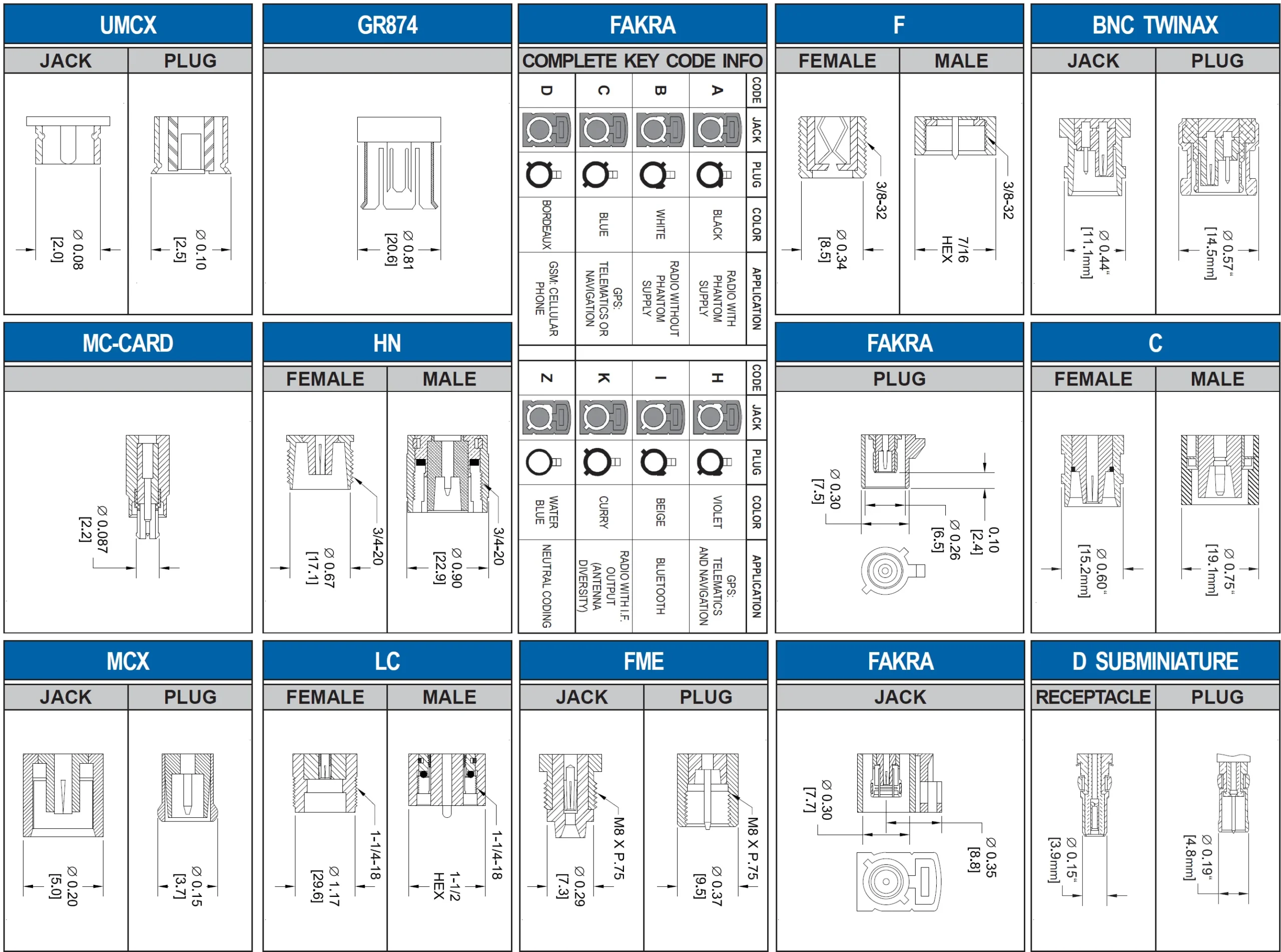
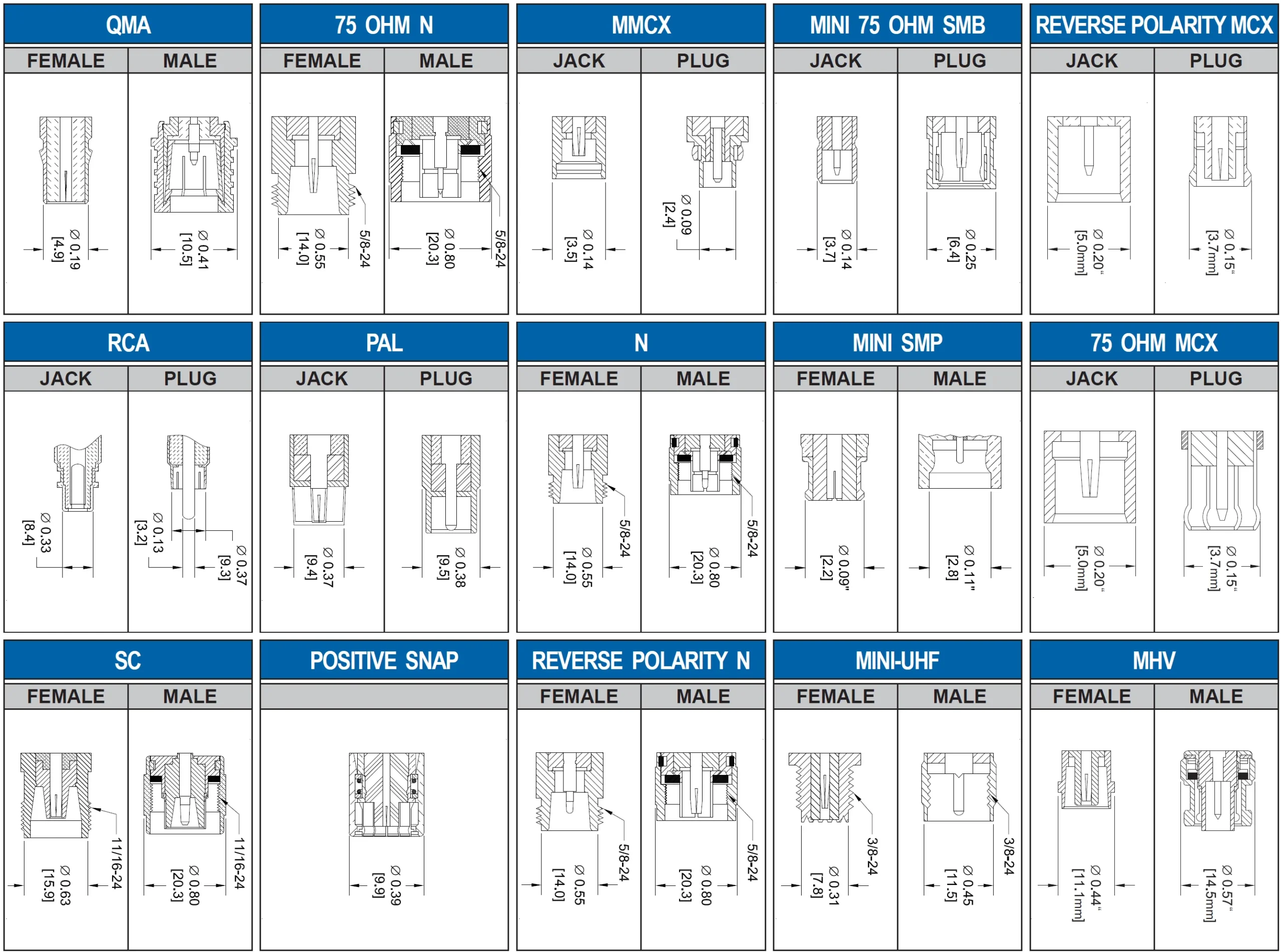
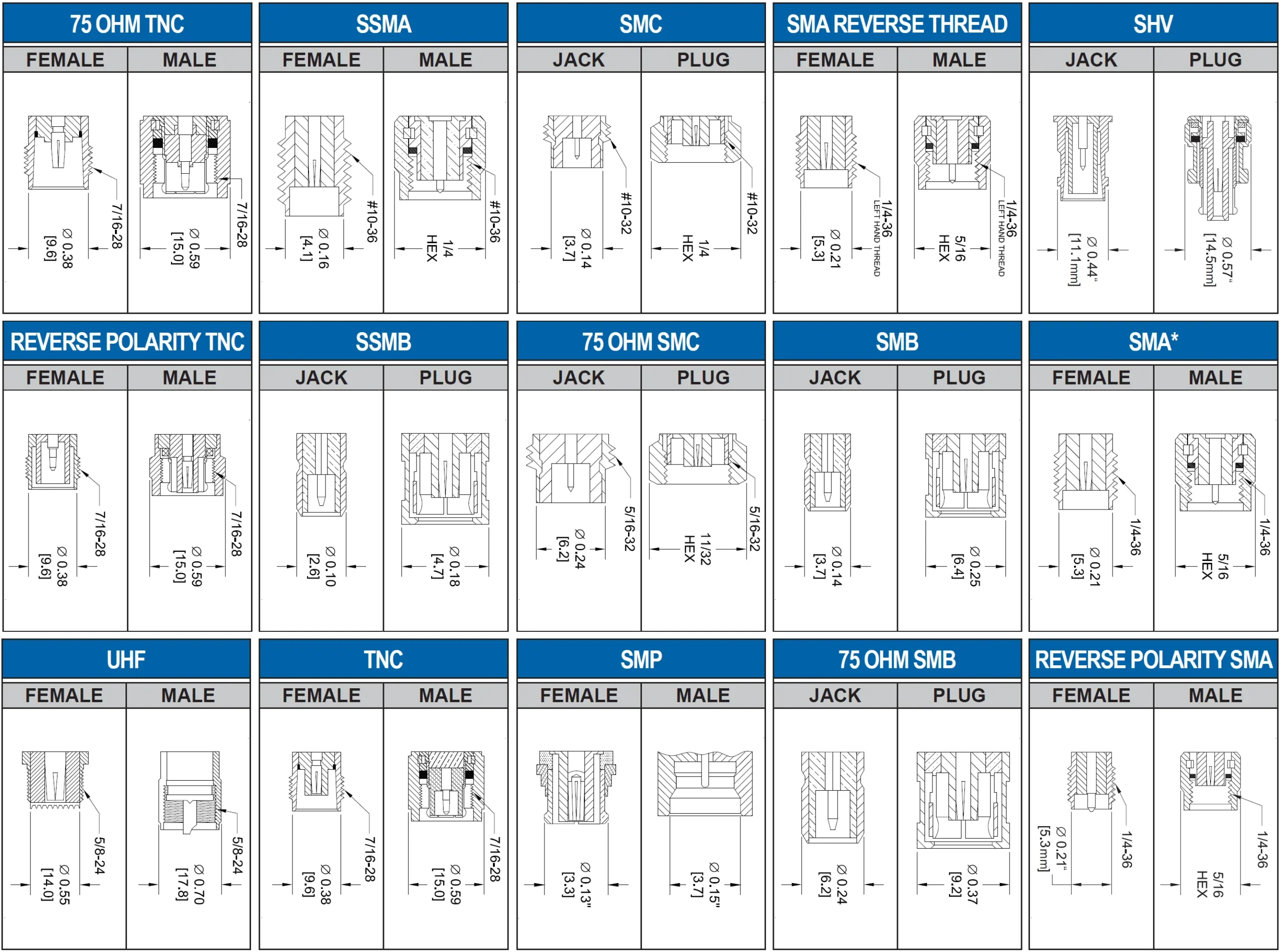
Even when paying attention to compatibility, it can be easy to confuse connectors due to the wide variety of types and their similarities. If they are not compatible, an adapter should be used. All types of connectors and their forms are listed in Annex 2, at the end of this document.
After making sure that the connectors are compatible we can start a visual inspection of the connector to ensure that it has no traces of dust or metal debris. If we find impurities, we must clean them before interconnection [1].
To make a good connections between two connectors, the following steps must be considered:
- carefully align the two connectors bringing them together along a common axis as shown in Fig. 9. Special attention must be given to connectors with a protruding male pin that engages with the female socket before the outer threaded conductor begins to mesh, to prevent damage to one or both inner conductors.
- turn only the outer connector nut (see Fig. 10). Avoid rotating one half of the mating assembly against the other, as this causes the mating surfaces to rub against each other. In particular, it leads to accelerated wear and a higher risk of damage to the male and female inner conductors. If the connector is clean and unaltered, at least half of the torque required to tighten can be done freehand. If we notice that tightening by hand is not possible or we need a lot of tightening force, it must be opened and checked because something is wrong.
- after we finish tightening the connector by hand, we need to come up with a torque wrench to complete the complete tightening to the required torque (see Fig. 11).
Each connector needs a torque specific to its type. If we are tightening two connectors on two cables, we must hold the connector that will be fixed with a wrench while we tighten the connector that must be threaded with the torque wrench [1][3].
When it comes to disconnecting connectors, certain aspects must be taken into account, just as carefully as during the connection process. Improper disconnection can also damage the connectors, making proper handling essential [3]:
- stabilize the devices to prevent any twisting, rocking, or bending forces on the connectors
- secure the device body with an open-end wrench to keep it from rotating
- use a second open-end wrench to loosen the connector nut
- finish disconnecting by hand, turning only the connector nut
- separate the connectors by pulling them straight apart [3]
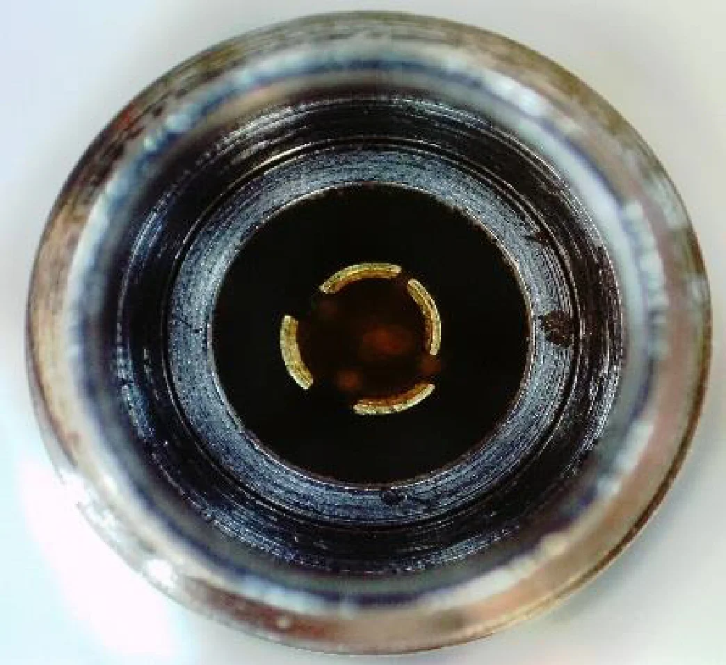
Figure 8. Bent fingers on female slotted connector [1]
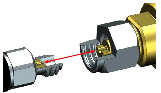
Figure 9. Align connectors together along a common axis [1]
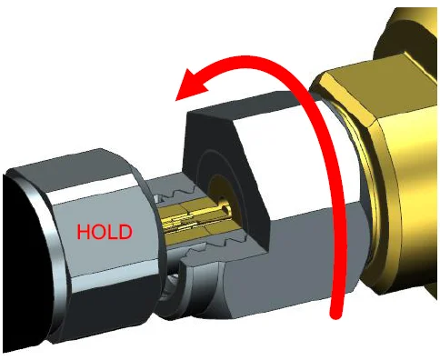
Figure 10. Finger tight connection, turning the nut only [1]
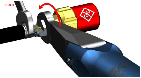
Figure 11. Tightening using a specialized torque wrench [1]
Handling coaxial cables tips
- bending radius
Avoid bending cables beyond the minimum recommended bend radius. Exceeding this limit can misalign the center conductor and deform the outer or center conductor, potentially leading to kinking or fractures. Such damage can degrade insertion loss and VSWR performance. Manufacturers typically specify two bending angles for cable assemblies: a dynamic bend radius and a static bend radius. As a general rule, the dynamic bend radius is approximately 4x (four times) the static radius. Larger-diameter cables generally require a larger bend radius [4].
- twisting
Cables should never be twisted. Excessive rotational torque can damage the cable assembly, particularly at the cable/connector junction or even along the cable itself, depending on how the twist is applied. Even minor twisting can cause measurement inaccuracies and introduce stress on test and device ports, potentially loosening connections. To minimize twisting, always connect angled connectors before straight ones [4].
- flexure
While cables are designed to be flexible, minimizing unnecessary bending helps extend their lifespan. If your measurements are highly sensitive to stability, consider using a fixture to prevent excessive movement after calibration. Repeated flexing can alter phase and amplitude performance. Always work with the cable’s natural curvature rather than forcing it against its natural shape [4].
- over-bending
The most common cause of cable damage is bending beyond the minimum bend radius, particularly near the connectors. Over-bending in this area can break the solder joint at the connector termination. If connections are too close together, leave a service loop to prevent excessive stress and bending.
- flex life
Cables have a finite number of bend cycles. While some manufacturers specify a minimum bend cycle count — sometimes exceeding 100,000 cycles— it is essential to understand what defines a cycle. Does it involve bending two (2) inches (5cm) at a 90° angle around a mandrel, or is it a ± 5° movement around a 12 inch (30cm) mandrel? With countless possible configurations, these specifications can be misleading. Since each application is unique, it’s important to use your judgment. Although cables won’t last indefinitely, proper handling and routing can significantly extend their lifespan and reduce costs [4].
Handling the torque wrench
Proper usage of a torque wrench is crucial to prevent potential damage to connectors caused by excessive torque application. Incorrect handling can result in over-tightening, which may compromise the integrity and functionality of the connectors. When using a torque wrench, it is essential to apply force precisely at the designated load point to ensure accurate torque delivery. As illustrated in Fig. 12, the correct load point is indicated in green. Deviating from this specified area can lead to an increased torque output, potentially causing mechanical stress and degradation of the connector components [1][2][3][4]. When using a torque wrench in combination with a fixed wrench, it is essential to maintain the correct angle between the two tools. This angle should not exceed 90°, as illustrated in Fig. 13. Additionally, it is important to tighten the connector only until the first “break” of the torque wrench occurs. Further attempts to continue tightening or forcing the wrench beyond this point should be avoided, as this can lead to over-tightening and potential damage to the connector [3].
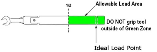
Figure 12. Ideal load point of torque wrenches [2]
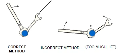
Figure 13. Correct and incorrect method to lift the torque wrench [3]
Maintenance and measurements
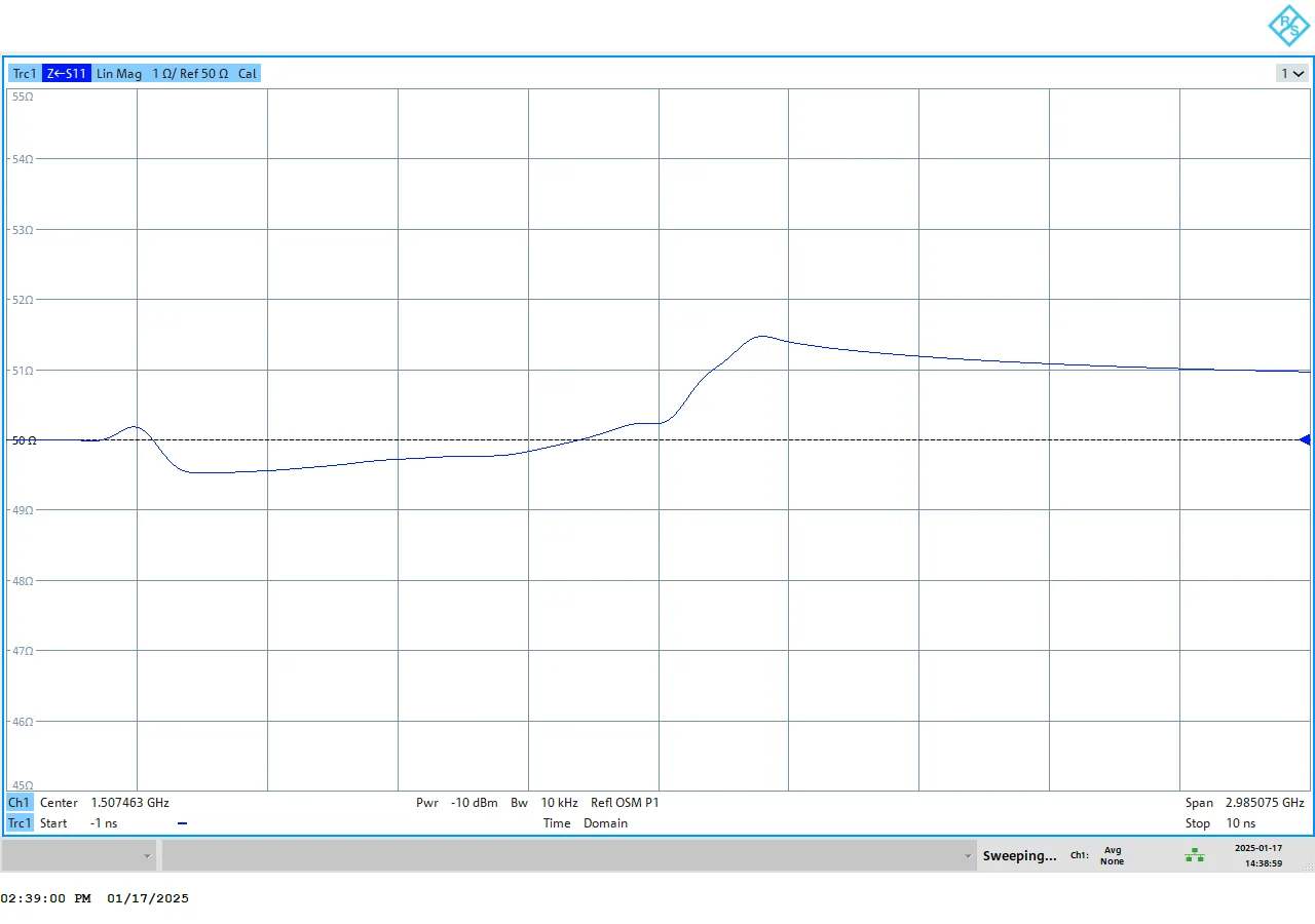
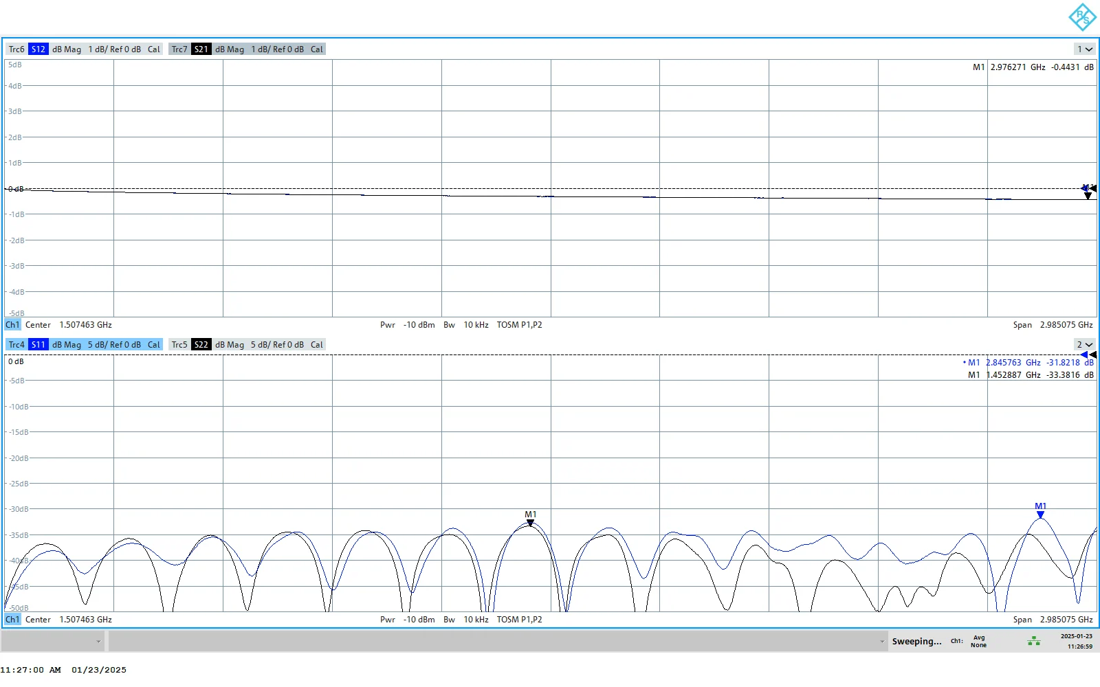
Even if we take all the necessary precautions for connectors and coaxial cables, over time they deteriorate (especially the connectors) and no longer perform as well as new ones. Therefore, at regular intervals (might be established by your laboratory routine and processes ), coaxial cables should be measured using TDR, and their S-parameters should also be evaluated to determine if the cable and coaxial connector still fall within the frequency range they are typically used for. One example below (Annex 3) shows usual measurements taken on various coaxial cable technologies and results. Of course, these kinds of measurements involve VNA or special TDR instruments for measuring coaxial cable assemblies.
References
1) Mark Bailey, Application Note, “Guidance on Selecting and Handling Coaxial RF Connectors used with Rohde & Schwarz Test Equipment | 1MA99”, Rohde & Schwarz®, “4.2015 – 1MA99_2e”, rev. 2e, Apr. 9, 2015
2) NI®, “RF Connector Care with NI Test Equipment”, Apr. 16, 2020 [Online] available at: “https://www.ni.com/en/support/documentation/supplemental/15/rf-connector-care-with-ni-test-equipment.html?srsltid=AfmBOor1-giTwoFhwvX5skowugINpqaj1V6M7EbehKl_v-j5T7YxY6vS”
3) Keysight®, “Connector Care” [Online] available at: “https://helpfiles.keysight.com/csg/m9485a/tutorials/connector_care.htm”
4) Megaphase®, Application Note, “Care and Handling of Cable Assemblies & Connectors”, [Online], available at: “https://megaphase.com/wp-content/uploads/2021/10/Cable-Connector-Care-White-Paper_10222021B.pdf”
5) Microwaves101.com, “Connector Care”, [Online] available at: “https://www.microwaves101.com/encyclopedias/connector-care”
6) Microwaves101.com, “Connector Torque”, [Online] available at: “https://www.microwaves101.com/encyclopedias/connector-torque”
7) Microwaves101.com, “How to (not) Trash a Calibration Kit!”, [Online], available at: “https://www.microwaves101.com/encyclopedias/how-to-not-trash-a-calibration-kit”
8) William W. Oldfield, Microwaves & RF, June 18, 2014, “Reaching Beyond 100GHz With Coaxial Connectors”, [Online], available at “https://www.mwrf.com/technologies/components/passive-components/article/21845760/reaching-beyond-100-ghz-with-coaxial-connectors”
Annex 1 – Connector Frequency Range Chart
Annex 2 (4 consecutive images) – RF Connectors Identifier (© copyright Pasternack Inc.)
Annex 3 – Below, examples of TDR and S-parameters measurements on Huber+Suhner® MULTIFLEX141 coaxial cable assembly (connectorized with Radiall® R125055000 SMA-, both ends). Measurements performed by ROWAVES® with Rohde & Schwarz ZNL-3, 5KHz to 3GHz VNA (© copyright ROWAVES® 2014-2026)